 |
Engineering & Environmental Information Services.
Geophysical consultants and contractors, Instrumentation and monitoring, Vibration & noise. |
Electromagnetic (EM) Ground Conductivity Surveys :-
Electromagnetic surveys are a useful means by which to detect changes in the sub-surface relating to changes in electrical conductivity. Electromagnetic ground conductivity surveys are used for environmental and engineering investigations in order to map out sub-surface changes which can be investigated using traditional intrusive methods. The method is particularly useful for the delineation of a landfill boundarys, mapping in-situ faoundations or concrete slabs and when attempting to locate lost landfill.
electromagnetic ground conductivity works by a transmitter coil inducing eddy currents in sub-surface materials which are detected by a receiver coil. Depending upon the orientation, spacing of the coils and frequency a variety of depths can be investigated. A range of instruments exist, including the Geonics EM38, EM31 and EM34, making it possible to investigate depths between 1.5m and 60m.
The EM61 produced by Geonics uses the time-domain principle to discriminate metallic targets from ground materials. It does this by measuring the length of time that the return signal from metallic targets persists. The system is frequently used for detection of unexploded ordnance, pile caps, drums and tanks.
Electromagnetic ground conductivity measurements are made by walking a series of predefined survey lines with no need for ground - instrument contact. The EM61 system is trolley based but is capable of being mounted directly on an operator. This adaptability makes EM methods ideal for surveying poorly prepared sites. Data loggers such as the Allegro Field Computer are used to capture instrument readings at set intervals. Using the dual serial ports it is also possible to capture both the instrument data and the GPS data with differential correction.
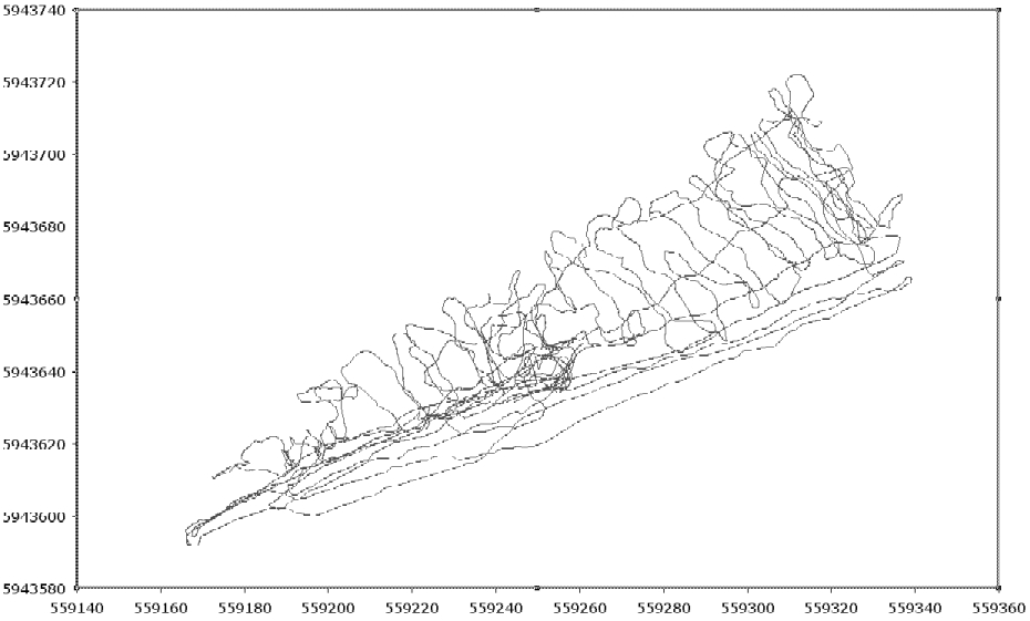
| On suitable sites GPS
reduces the need for setting out survey lines. Setting out accurately on some
sites would be nearly impossible but with GPS only a few key fixed points are
needed for position and closure checks. The image (right) shows the track taken during a conductivity survey.
|
 |
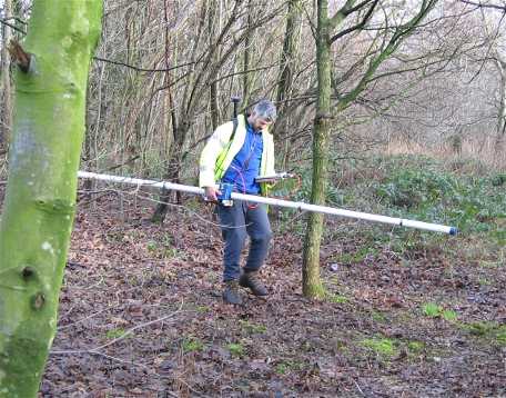
| The photograph (right)
shows an EM31 survey in progress with real-time Differential GPS positioning. The Differential GPS antenna is located behind the operators head. Laying out survey lines with tapes would be impossible on sites with so much surface vegetation. |
 |
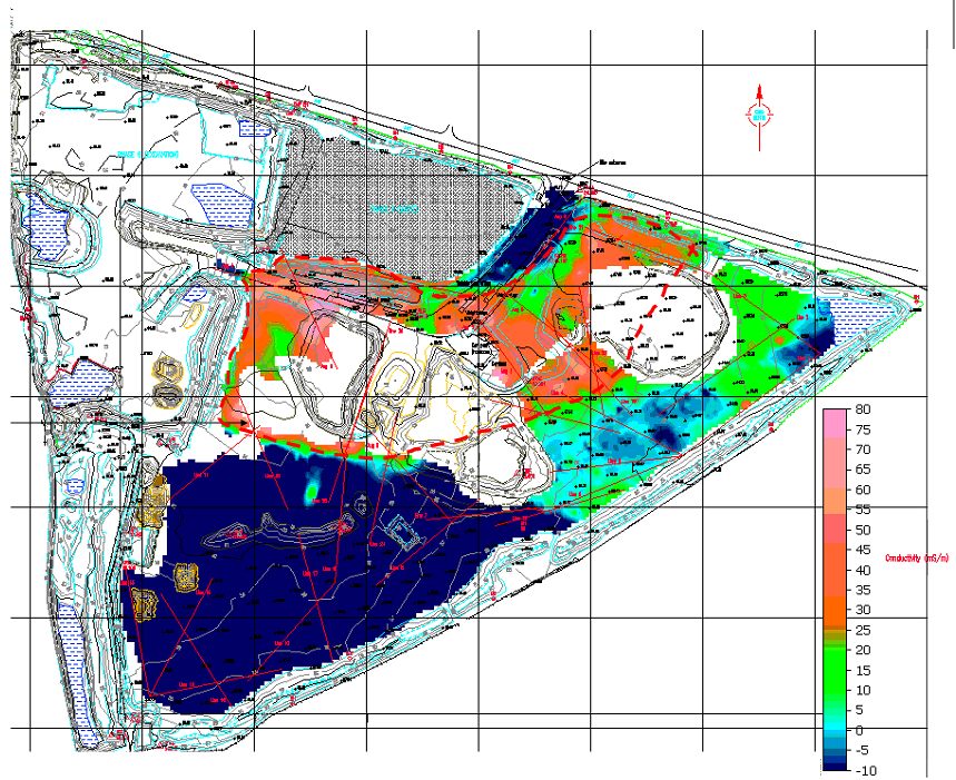
At the end of each survey day the data are downloaded to PC for a rapid assessment of the survey success and findings. Processed data are often superimposed upon existing topographic surveys. The image below shows typical final output from a conductivity survey over an former gravel pit with infill ranging from rock waste to putrescible waste. The only way to find out the distribution of buried materials without the geophysical approach is to use trial pits and boreholes and to make considerable assumptions from their "spot-reading" nature.
|
|
Applications :-
- Pollution plumes
- Landfill boundaries (EPA Part IIA
asessments)
- Brownfield sites
- Unexploded ordnance
- Mineshafts
- Quarries and opencast
- Pipelines, reinforced slabs, drums,
infill
- Agricultural soil moisture mapping,
also for sports grounds.
Benefits :-
- Rapid surveying - walking speed or discrete measurements
- GPS compatible - little setting out required
- Instruments for a range of depths
- Non-intrusive
- Quick analysis and reporting