 |
Engineering & Environmental Geophysics Services.
Geophysical consultants and contractors, Instrumentation & monitoring, Vibration & noise. |
Ferroscan
Microgravity
Soil thermal
resistivity / Soil thermal conductivity
Engineering Geophysics:- Seismic refraction & reflection surveys
By imparting a large energy pulse into the ground using a hammer, drop weight or cartridge explosive a series of geophones are used to detect the seismic energy returning to the ground surface. The energy arrives at the geophones either directly along the ground surface, by reflection from layers or interfaces or by refraction from the top of a layer. Using the return time of the energy we can calculate velocity, model the presence of layers, and find ground stiffness and rippability. Using continuous surface waves (CSWS) generated by a vibrating mass it is possible to obtain ground stiffness profiles for geotechnical purposes within 50 minutes. The method can be used on contaminated land and difficult sites as it is non-intrusive.
Concrete Floor Slab Surveys - Ferroscan reinforcement mapping surveys
| Although not usually classed as geophysics, the Hilti Ferroscan is used for the mapping of steel reinforcement & mesh in concrete. The instrument gives an almost instant visual image - very useful for on-site decision making and concrete slab and column surveys. The Ferroscan is capable of imaging the uppermost reinforcement layers and detemining the diamter of the rebars. GPR surveys compliment the Ferrscoan surveys as they can image the deeper reinforcement although GPR cannot estimate rebar sizes. |
 |
Microgravity surveys
Measurements of local gravitational field can be taken with exceptionally sensitive instruments. By measuring the variation in gravity over a tight grid its possible to model the data to obtain information on the location of voids, infilled karst features, buried channels and buried structures. Although a relatively slow method due to the precise levelling needed between each survey station the output can be worthwhile since the system measures passively and is not affected by electrical or conductive interference and can be used in industrial buildings where vibration is kept to a minimum.
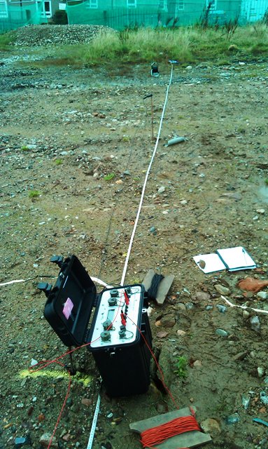
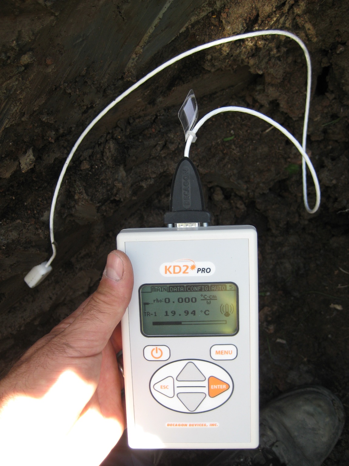
Underground Cable Specification - Soil thermal resistivity & thermal conductivity testing surveys
| Cable engineers use measurements of soil thermal resistivity / thermal conductivity to design power cable installation schemes. A number of incidents have occurred in the past where the soil around a cable under high load was not able to conduct heat quickly enough to prevent thermal runaway and subsequent damage. We use the KD2 soil thermal resistivity / conductivity probe to provide in-situ measurements. Measurements can be made along a proposed cable route at set intervals relatively quickly allowing the route to be fully assessed prior to final route choice. The method can also used for obtaining the soil thermal properties before design and viability assessment of geothermal ground heat systems both domestic and industrial. |
 |
Earth Grid Design - Sub Stations and Wind Farms - Soil electrical resistivity testing & Soil corrosivity
Typically soil electrical resistivity is measured using the 4 electrode Wenner resistivity technique and a suitable resistivity meter. Other meaurement configurations such as Schlumberger Palmer can be used if appropriate. A test point close to proposed earth grid installation is chosen or numerous measurements can be made along the proposed cable route. At each test point earth resistance measurements are taken by expanding the electrode spread to gain soil resistivity data at a range of depths or at a continuous depth. We can supply either raw soil resistivity data or can model the data to show how the soil resistivity changes with depth and differing layers of strata.
The measurement of soil electrical resistivity can be important along pipe routes to assess the potential soil corrosivity. Here measurements of soil resistivity are made at intervals along the pipe route at a depth corresponding to the installation depth. This can be achieved from the surface by using an appropriate electrode spacing to account for changes in the installation depth over the pipe route.